3D printed Pi Pico solder holder
When you buy a Pi Pico the cheapest option is to buy the basic pcb board without the pins fitted. You can then fit two 20-way pin arrays and solder them to the board yourself.
One way to do this is by using a breadboard to hold then pins in place while you solder them to the Pi Pico. You have to be careful though to use an equal pressure (on top of all the pins) when you pish them in, otherwise the pins can get out of vertical alignment. Further, the heating resulting from soldering the pins is not great for the breadboard. Here I have created a 3D printed holder to make this easier. A piece of (non copper track) vero / perf board is slid into the device and this is used to hold the pins and Pi Pico in place when soldering (the vero board takes the heat not the 3D plastic) - see photos and captions below.
I also printed pilot holes for a bolt to go into the sides of the holder. Using a bolt and butterfly nut you can tighten this up to secure the vero board. You may need to drill-out the bolt holes to suit the bolt you use.
First solder the outer four pins (ie. pin 1, 20, 21 and 40) then once you are happy that the pins are straight and correct, solder all the rest.
This holder is also a stable way of holding the Pi Pico when it not on a breadboard and stops it 'floating around' when its just on a usb lead into a computer etc.
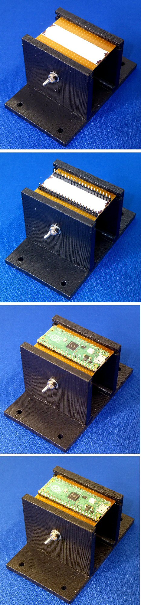
Photos:
Top photo: holder with vero / perf board (Note: use board with no copper tracks) 50 x 37 mm, 20 hole x 14 hole, slotted in and butterfly bolt slightly tightened
Second photo: holder with 2 x 20 pins fitted at correct seperation
Third photo: Pi Pico fitted onto these pins
Bottom photo: 40 pins soldered to Pi Pico pcb
Dr Jonathan Hare, E-mail: jphcreativescience@gmail.com
NOTE: Although none of the experiments shown in this site represent a great hazard, neither the Creative Science Centre,
Jonathan Hare nor The University of Sussex can take responsiblity for your own experiments based on these web pages.
THE CREATIVE SCIENCE CENTRE
home | diary | whats on | CSC summary | latest news